Ultrasim® for Infinergy®: Optimize processing and part performance
Ultrasim® is the versatile and flexible CAE competence for your innovations using Infinergy®. Our calculation of component concepts on a virtual basis starts with appropriate materials and adequate material models, ranging from the virtual prototype and ideal manufacturing process to the finished mass-produced component.
ULTRASIM® IS WHAT YOU NEED!
Why? Convince yourself:

Ultrasim® offers a unique combination of CAE tools and material know-how. That opens up the possibility of predicting part performance - even before manufacturing the first prototype.
It creates a digital twin by taking into account variables that influence part performance. This way, it allows to optimize the part design and support you along the processing chain to achieve your goals.
Do you need help?
Feel free to contact our experts!
Our experts are always happy to help you.
No matter what!
Click here to jump directly to the contact formular
How does the process for Infinergy® look like in detail?
Have a look at every step in detail:
Achieving optimal packing by optimizing:
- filler location and orientation
- mold orientation
- venting
Defect prediction:
- detect voids
- predict packing inhomogeneities
- predict fluid flow and particle trajectories by accounting for particle-particle and particle-fluid interaction
- material characterization guarantees predictive power
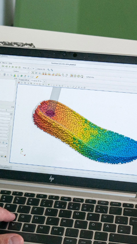
- cutting-edge simulation framework for particle flow by coupling Computational Fluid Dynamics (CFD) with Discrete Element Method (DEM)
- simulation of filling behavior as a customer service
- realistic prediction of particle packing and voids
- reduced need for prototyping
- advanced process optimization
In the second processing step, the mold is closed while steam is applied. Thereby the beads are squeezed into the voids that formed during the initial filling phase. The goal of the crack closing simulation is to predict the final size and location of voids while using the beads packing from the filling simulation as starting point. With a larger crack it is easier to remove all voids but that comes at the cost of heavier and more expensive part. The simulation can be used for finding the minimal crack that yields an acceptable part.
Also different Infinergy® types can be tested.
The upper row shows crack closing simulations for Infinergy® 230 for different cracks applied (left to right): 5 mm, 10 mm, 20 mm.
The lower row shows the same crack closing simulations but here, Infinergy® 210 MP is considered. The color indicates the pressure (blue=low, red=high) in the material. Low pressure regions are prone to voids. The simulation demonstrates that, in general, larger cracks lead to nicer top lines. Furthermore, for a given crack, Infinergy® 210 MP yields nicer top lines compared to Infinergy® 230.
- virtual mechanical part testing and part optimization
- support for static structural simulation including cyclic load cases
- material model accounts for stress softening and hysteresis
Perform virtual part testing and optimization
The elastomeric foam model in Ultrasim® accounts for compressibility up to large deformations
Generate force-displacement curves for structural load cases while accounting for stress softening and energy dissipation in cyclic loading
Possible Simulation Support for 3D Lattice Inserts
Filling Simulation
- mold filling with inserts possible
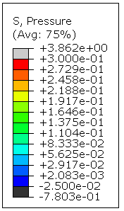
- prediction of density or void distribution
Part Simulation
- hybrid parts of Ultrasint® and Infinergy® can be simulated
- prediction and optimization of sole stiffness